Many of you may have used PCIe Screamer by LambdaConcept and variants with firmware by U. Frisk, for all sorts of activities from physical pentests, bypassing antiviruses, bypass anticheat products in games, and so on. In this blogpost @astralvx will explain the PCIe packet TLP used in bus mastering/DMA.
Introduction
Direct Memory Access (DMA) is a way to transfer data between a hardware peripheral and system memory at high speed without OS restriction.
DMA devices that need high speed transfer include gigabit speed network cards, storage cards, graphics cards, sound cards, etc. DMA capable connections include PCI, PCIe, Thunderbolt, FireWire, ExpressCard.
The malicious use cases for DMA is an adversary with physical access could do a ‘drive by’ attack by removing the machine chassis or inserting via TB3, and performing DMA from your device into any of system/physical memory and do anything malicious from patch kernel memory, bypass code integrity, install hooks to install kernel implants. At the end we also discuss the OS mitigations against this.
PCI bus vs PCIe
PCI bus is a true bus, whereas PCI Express (PCIe) is like a network that is packet based (dealing with addresses, reads, writes, interrupts) that leverages the PCI bus. This allows for backwards compatibility with legacy PCI devices. Root Complex is the root of all I/O transaction and sits between CPU and main memory and devices.
Intended use
Legitimately the way PCIe devices and DMA are supposed to interact is as follows. The OS creates a memory mapped (MMIO) region and writes the system address into a Base Address Register (BAR) of the device’s PCI Configuration Space. The corresponding kernel driver to your device allocates from kernel pool and transmits the physical address through the MMIO BAR into the register space of the device. The device can then act as a bus master and send read/write DMA transactions directly to your transmitted physical address, and signal an MSI interrupt once DMA is complete, so your driver’s interrupt handler is notified.
There is no requirement to DMA on your assigned system memory, you could read/write to any system address via DMA.
However when VT-d and DMA protection is enabled, drivers needs to support DMA remapping otherwise the IOMMU will block undeclared DMA transactions. More explained at the end.
Bus Master Enable
The platform firmware needs to grant a PCI device the Bus Master Enable (BME) bit in the PCI Configuration Register, then that device can act as a bus master and send read/write TLPs just like the Root Complex. However a poorly developed or malicious peripheral can still send TLPs up the PCI bus regardless of BME bit being set.
Bus transaction example
The Transaction Layer Packet (TLP) is 3 layers consisting of:
- The Transaction layer deals with the assembly and disassembly of TLPs. TLPs are used to communicate transactions, such as read and write, as well as certain types of events.
- The Data Link layer deals with Link management and data integrity, including error detection and error correction.
- The Physical layer relates to input buffers, physical link and encoding technology.
If the CPU wants to perform a read/write operation on a peripheral, then the chipset (for PCIe this acts as a Root Complex) generates the TLP and transmits it over the one of many chipset PCIe ports, then the TLP is routed over the PCIe network to the target peripheral.
TLP format
Different types of TLP have different formats, but all will have the TLP header (4 bytes) which is used to determine the type and size of the packet. Find out more in the PCI Express specification, linked at the end.
Read request TLP
Let’s create a Request TLP to send from PciLeech (requestor) to Root Complex (completer) to read System PML4 at system (physical) address 0x001AD000 and read 128 bytes. Since it’s a 32bit address we only need a TLP of 3 dwords, else for 64bit we need 4 dwords.
pcileech.exe tlp -vvv -in 000000203f0080ff001ad000
- Format/Type = 0y000 0y00000, which is Memory Read request
- Length = 0x20, where this is elements of dword size, so the byte length is 0x20*4=128
- Requestor ID = 0x3F00, is PciLeech B/D/F 63/0/0 or 3f00, which can be found in device manager under Details -> Property [Location information]
- Tag: 0x80 (arbitrary tracking number)
- First/Last dword byte enable = 0xFF (essentially acts as an offset from start/end)
- Address: 0x1AD000

Completion TLP with data
A Completion TLP is then returned to PciLeech after the Root Complex has obtained the data we requested.
4a 00 00 20 00 00 00 80 3f 00 80 00 67 b8 c4 48
08 00 00 8a 00 00 00 00 00 00 00 00 00 00 00 00
00 00 00 00 00 00 00 00 00 00 00 00 00 00 00 00
00 00 00 00 67 28 c0 6e 00 00 00 8a 00 00 00 00
00 00 00 00 00 00 00 00 00 00 00 00 00 00 00 00
00 00 00 00 00 00 00 00 00 00 00 00 00 00 00 00
00 00 00 00 00 00 00 00 00 00 00 00 00 00 00 00
00 00 00 00 00 00 00 00 00 00 00 00 00 00 00 00
00 00 00 00 00 00 00 00 00 00 00 00
- Format 0x4A[5:7] 0y010, completion with data
- Type: 0x4A[0:4] 0y01010, completion with data
- Length: 0x20, again in count of dword elements so 0x20 * 4 = 128
- Completer ID: 0x0000 (Root Complex)
- Completion status: 0x0 (Success)
- Byte count: 0x80 (128, as requested in request packet)
- Requestor ID: 0x3F00 (PciLeech BDF)
- Tag: 0x80 (just as sent in request packet)
- Lower address: 0x00 (last 7 bits on our request address)
- Data: 128 bytes worth of data at physical address 0x1AD000
Write request TLP
Very similar to Read Request TLP, but the end of the packet contains the payload data to be written at target address. Here’s a nonsensical sample to overwrite System PML4 entry with 0xAAAAAAAABBBBBBBBCCCCCCCC.
pcileech.exe tlp -vvv -in 400000033f0000ff001ad000aaaaaaaabbbbbbbbcccccccc
Now let’s verify in Windbg by dumping physical memory, and PML4 entry has been overwritten. Of course the moment I resume in Windbg, the machine crashes due to an invalid PML4, I’m sure you have better addresses to overwrite 😉
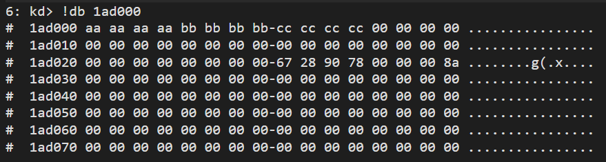
A real use case is to patch a DLL in some process – get System PML4, find patterns for System eprocess, walked linked list to target process, get PEB, get loaded modules linked list, find your target DLL, get the image base address, do your patch.
Payload data size
Every TLP carrying data must only send up to the max payload size set during initialization (typically 128, 256 or 512). To send more, multiple TLP completions can be sent. In the typical setup TLP packets will arrive in order, unless the Relaxed Ordering is explicitly set in the TLP.
Mitigations
Whilst DMA is extremely powerful, a security mitigation was introduced to limit the potential of hardware peripherals. The IOMMU (Intel VT-d) applies a concept of virtual memory to system buses where a Virtual Machine Monitor (VMM) aka hypervisor acts as a host and has full control of the platform hardware.
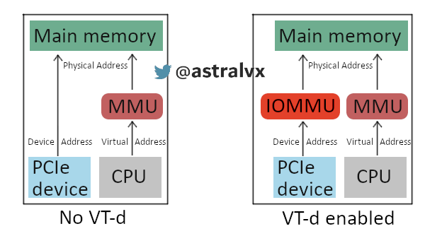
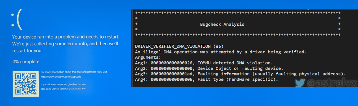
The hypervisor presents the OS with an abstraction of physical memory. DMA remapping (DMAr) translates the address of incoming DMA requests to the correct physical memory address and does access permissions checks, on any non-success a fault is generated. However this all relies on OS drivers supporting DMAr, as they need to inform the IOMMU about the DMA ranges the device will access. Without this Pcileech or other PCI/e devices can not bus master/DMA on modern systems with security protections like “Kernel DMA protection” enabled as the IOMMU will block your undeclared DMA transaction resulting in:
References and further reading
PCI spec – PCI_Express_Base_4.0_Rev0.3_February19-2014.pdf
Kernel DMA protection – https://docs.microsoft.com/en-us/windows-hardware/design/device-experiences/oem-kernel-dma-protection
More details on TLP packets – http://xillybus.com/tutorials/pci-express-tlp-pcie-primer-tutorial-guide-1
Screamer M.2 FPGA – https://shop.lambdaconcept.com/2-home
Pcileech to craft TLPs – https://github.com/ufrisk/pcileech